Magnetic Transducer for the acoustic components - fbelec.com | FBelec
Magnetic Transducer for the acoustic components
2024-06-05
  • Operating Principle of Magnetic Transducer

    The operating principle of a magnetic transducer is herein described. The magnetic flux from a magnet produces a bias magnetic field at the tip of the iron core, drawing a diaphragm toward itself by a suitable force. If electric signals (for example, rectangular shaped voltage with a frequency of 3.2 KHz and 1.5 Vo-p) coming intermittently at a fixed frequency from an external oscillating circuit are input, an electric current will intermittently flow through the coil, generating an intermittent magnetic field at the tip of the iron core.

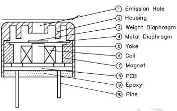
  • Cross-section of Magnetic Transducer
  • The magnetic field drives the diaphragm up and down, generating the sound pressure corresponding to the amplitude of the diaphragm. This sound pressure is further multiplied by the resonance effect of the resonator installed on the case. Each product is designed and adjusted based on resonance frequency (fo) and resonance frequency (fv), so that excellent performance is obtained at the standard frequency. Accordingly, the functional composition of a magnetic transducer can be divided into the magnetic circuit unit, and the resonance unit.

    Measuring Circuit

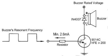
    Electric signals of a specific frequency to a magnetic transducer, using the measuring circuit to measure the characteristics of the acoustic components. Please use this information in measuring your acoustic components and arranging driving circuits.

  • Magnetic Transducer Driving Circuit

  • Magnetic buzzer

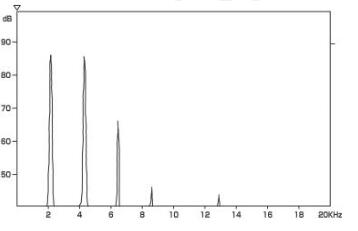
    Magnetic Buzzer and Transducer Fig. 6 shows how the peep sound is composed of a collected body of the fundamental frequency and its integer fold frequencies. This sound composed of integer fold frequencies is generally referred to as a single sound which has a clearer tone than the low pitched buzzers have.

  • Magnetic Buzzer FFT analysis

  • Magnetic transducer are usually built into equipment and used in that state. At that time, users may have various needs, such as "raising sound pressure" or "widening the frequency band." By installing a resonator on the case in which the magnetic transducer is contained, etc., it is possible to make sound characteristics closer to these requirements. On this occasion, the "resonance effect of Helmholtz," which can be used for reference purposes, is hereby introduced. To improve the characteristics, it is possible to widen the frequency band or to raise the sound pressure of the standard frequency or desired frequency by setting the resonance frequency (fv) of the external resonator for the magnetic transducer use at a level slightly higher than double the standard frequency, a desired frequency close to it, or the consonance frequency (fo) of the sounder. The resonance effect formula of Helmholtz represents a heoretical formula that demonstrates the relationship between fv of the external resonator and the size of the resonator. Because the effect of the resonator incorporated in the magnetic transducer is not included, it is necessary to take the acoustic combination with the resonator of the magnetic transducer in actual setting. The usual method is to incorporate the magnetic transducer in the real body of the external resonator and adjust its sound emission hole, etc., while considering the value, calculated through the formula, and to seek optimization.

CONTACT US

  • E-mail: sales@fbelec.com
  • Tel: 86-574-87793491
  • Add: 262#416Lane ZhaoHui Road YinZhou NingBo China
  • Phone: 18868647636
  • wechat

Copyright © 2021 NINGBO FBELE ELECTRONICS CO.,LTD. All Right Resrved Designed by www.followala.com

Sitemap | XML | Blog

×

Hello!

Welcome to text me on WhatsApp or send me an email to sales@fbelec.com

× Text me on whatsapp