Arduino Oscilloscope
Before we dive into the Arduino version, let's quickly recap what an oscilloscope does.
In essence, it's an electronic test instrument that graphically displays voltage signals as waveforms on a screen. This allows you to analyze various signal characteristics like:
Amplitude (Voltage): The vertical size of the waveform.
Frequency: How often the waveform repeats.
Waveform Shape: The overall shape of the signal (sine wave, square wave, etc.).
Why Build an Arduino Oscilloscope?
While an Arduino oscilloscope won't replace a professional-grade instrument, it offers several compelling advantages:
Cost-Effective: It's significantly cheaper than a dedicated oscilloscope.
Educational: It provides a fantastic hands-on learning experience in electronics and programming.
Customizable: You can tailor it to your specific needs and add features.
Portable: It can be easily powered by USB, making it highly portable.
An Arduino oscilloscope works by using the Arduino's Analog-to-Digital Converter (ADC) to sample the input voltage at regular intervals. These samples are then processed and displayed as a waveform, often using a connected LCD screen or by sending data to a computer for visualization via serial communication and software like Processing.
Arduino Board (Nano recommended): The brains of the operation.
Connecting Wires: To connect the components.
Resistors: For voltage division and protection.
Optional: LCD Screen: For displaying the waveform directly.
Optional: Breadboard: For prototyping the circuit.
Basic Circuit and Code Overview
The basic circuit involves connecting the signal you want to measure to an analog input pin on the Arduino (e.g., A0). Resistors are often used to create a voltage divider to ensure the input voltage stays within the Arduino's safe range (0-5V).
Performs the following steps
Read Analog Input: Read the voltage value from the analog pin using analogRead.
Process Data: Convert the raw ADC reading to a voltage value.
Display Data: Display the voltage value on the LCD or send it to a computer for visualization.
Challenges and Limitations
It's crucial to understand the limitations of an Arduino oscilloscope
Limited Bandwidth: The Arduino's ADC has a relatively low sampling rate, limiting the maximum frequency it can accurately measure.
Limited Resolution: The ADC has a limited resolution (typically 10 bits), which affects the accuracy of voltage measurements.
Noise: The readings can be susceptible to noise.
Several techniques can be used to improve the performance of an Arduino oscilloscope
Using an External ADC: Connecting a dedicated external ADC with a higher sampling rate and resolution can significantly improve performance.
Over-Sampling: Taking multiple readings and averaging them can reduce noise.
Proper Shielding: Shielding the circuit can help reduce interference.
Software for Visualization
While an LCD can be used for basic waveform display, software like Processing offers more advanced visualization capabilities on a computer. Processing can receive data from the Arduino via serial communication and display it as a scrolling waveform, providing a more traditional oscilloscope-like experience.
FBelec oscilloscope provides professional functionality available at lower bandwidths. oscilloscope manufacturers in China. Applied to the internet world Electronics & Computer Industries.
In the world of electronics enthusiasts, an oscilloscope is an indispensable tool that can display electrical signals in intuitive waveforms, helping us uncover the secrets hidden in circuits. Today, the protagonist is a charming Arduino oscilloscope that is entering the field of electronics enthusiasts in a unique way, embarking on a wonderful journey of exploration.
The Arduino oscilloscope, although not as precise and complex as professional grade oscilloscopes, has unparalleled user friendliness and openness. For those beginners in the electronics field or DIY enthusiasts, Arduino oscilloscopes are like a key that unlocks the door to electronic signals. It is based on an Arduino development board and can be easily built with some simple peripheral circuits. This means that you don't need to spend expensive money on professional equipment, and with just the basic materials at hand, you can have your own oscilloscope to monitor voltage changes in the circuit at any time.
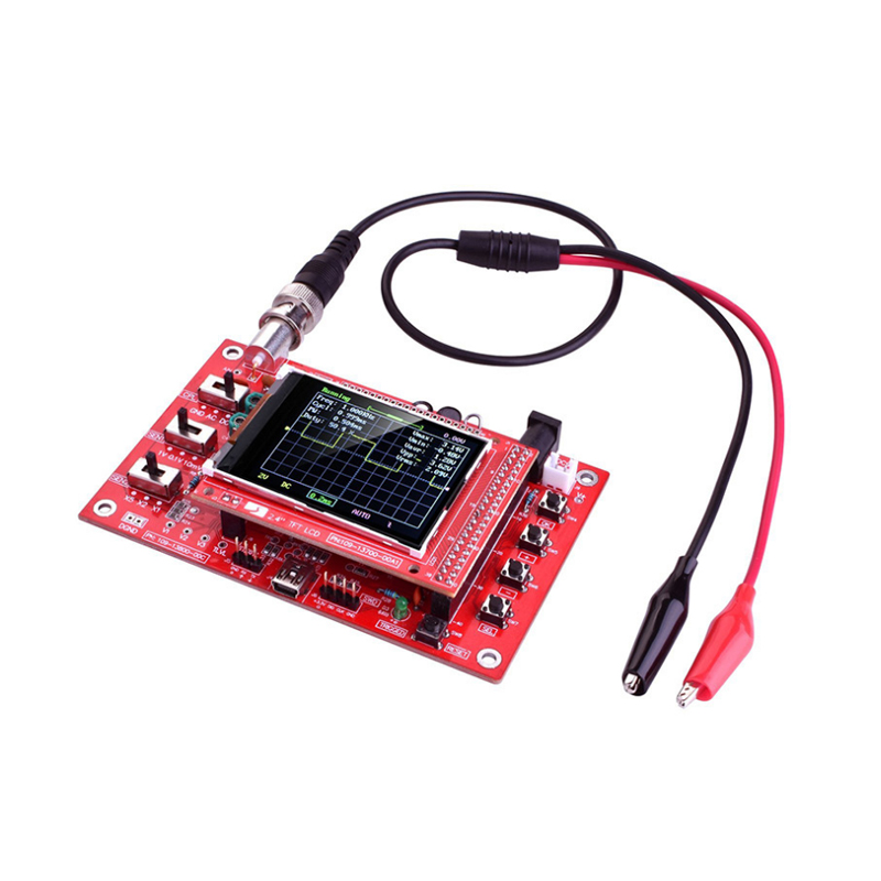
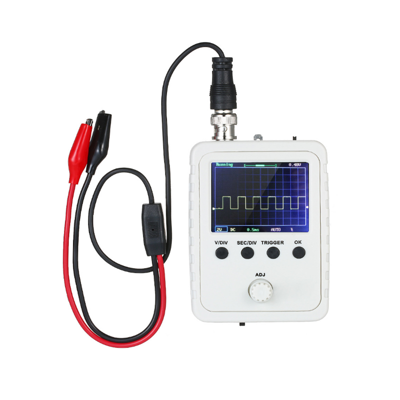
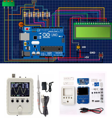
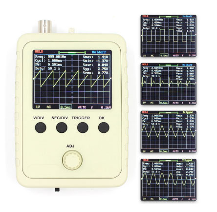
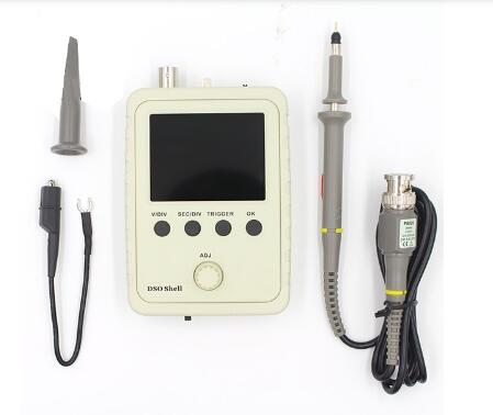
Imagine that when you are debugging a self-made small speaker circuit and want to figure out if the audio signal output is normal, an Arduino oscilloscope can come in handy. It can capture the waveform of audio signals in real time, allowing you to clearly see the fluctuations of sound and accurately locate possible problems, whether it is signal distortion, frequency deviation, or amplitude anomalies, there is no escape. Moreover, as it is based on the Arduino platform, you can flexibly expand the oscilloscope functions according to your own needs. Do you want to increase the frequency range of the measurement signal? No problem, just modify the code and adjust the circuit parameters to easily achieve it. This highly customizable feature gives users great creative freedom, making the journey of exploring the electronic world full of infinite possibilities.
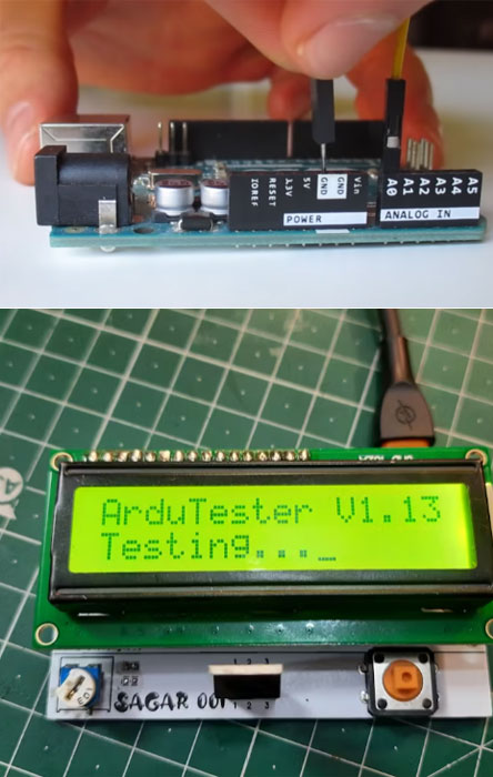
Not only that, Arduino oscilloscopes also provide excellent assistance for electronic education. In class, students can build and program oscilloscopes themselves, gaining a deeper understanding of their working principles, rather than simply memorizing abstract concepts from textbooks. Through practical operation, they can witness firsthand how electrical signals are transformed into intuitive waveforms. This experiential learning method undoubtedly greatly stimulates students' interest and enthusiasm for electronic technology, sowing the seeds of hope for cultivating future electronic engineers.
In this era full of creativity and exploration, Arduino oscilloscopes are like a brilliant new star, illuminating the path of amateur electronics enthusiasts and injecting new vitality into the popularization and education of electronic technology. It provides more people with the opportunity to delve into the electronic world, discover and create, and embark on their own technological journey.
DSO138 digital oscilloscope kit engineering and DIY handheld oscilloscope dso oscilloscope |
Shell oscilloscope kit DSO150 electronic teaching and training DIY kit with Euro gauge power supply + BNC probe |
BNC Oscilloscope Probe P6100 100MHZ Oscilloscope Probe/Probe |
DSO150 oscilloscope finished 15001K DIY digital oscilloscope kit with case digital oscilloscope |
FNIRSI DSO168 digital oscilloscope 20M bandwidth 100M sampling rate handheld mini oscilloscope |
DDS low frequency signal generator sine wave square wave triangle wave ECG sawtooth wave |
Shell oscilloscope production kit DSO138 upgrade version DSO150 electronic teaching training DIY kit |
DSO150 Oscilloscope kit Electronic training DIY kit DSO150 loose parts with power supply |
Shell oscilloscope production kit DSO150 electronic teaching practice DIY kit DSO150 finished kit |
Copyright © 2021 NINGBO FBELE ELECTRONICS CO.,LTD. All Right Resrved Designed by www.followala.com
Welcome to text me on WhatsApp or send me an email to sales@fbelec.com