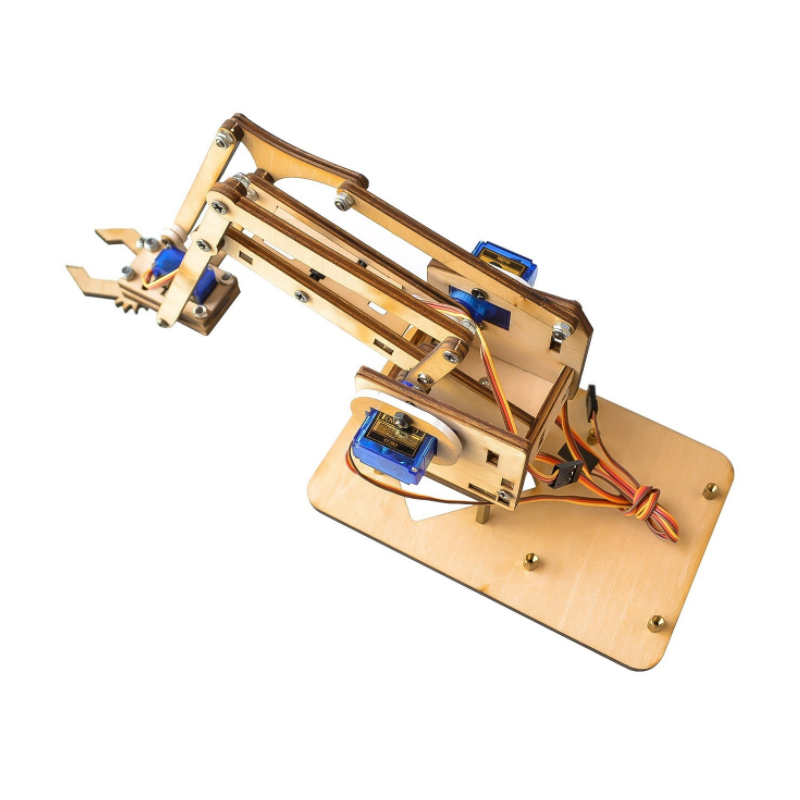
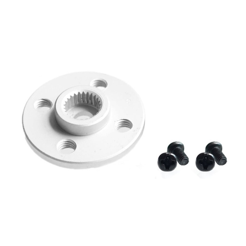
What is Steering Engine?
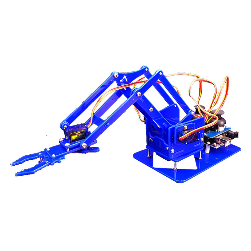
1. Introduction to Steering arduino robot
Structural composition
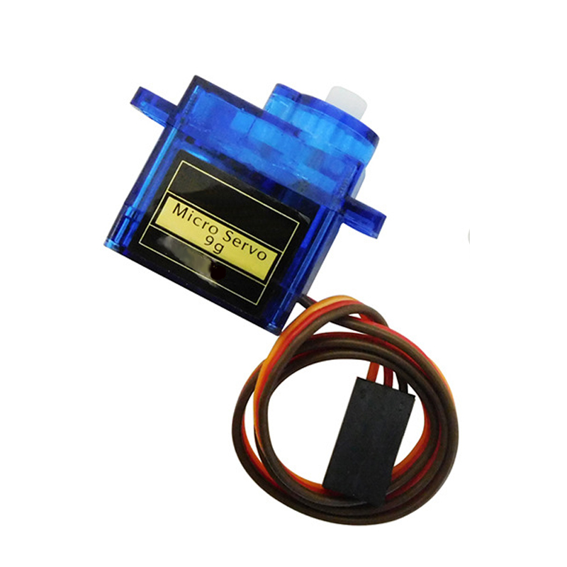
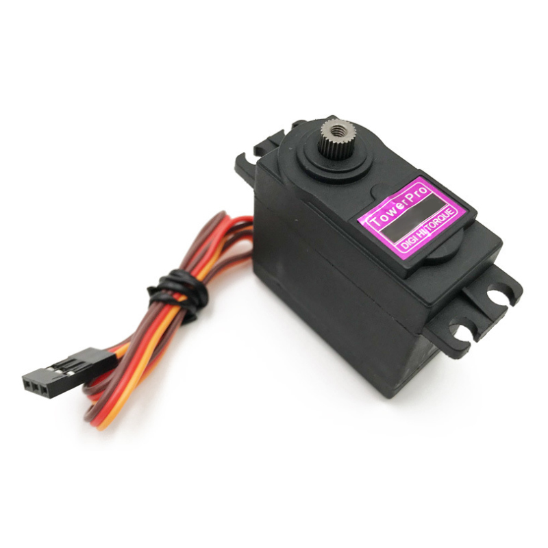
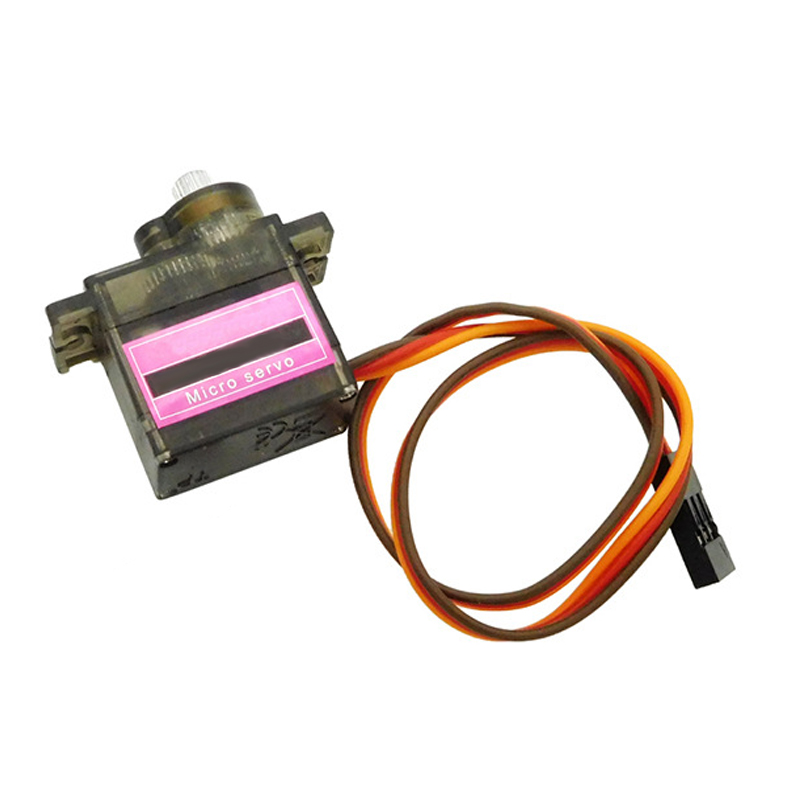
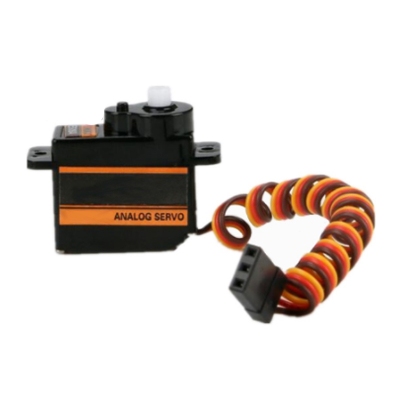
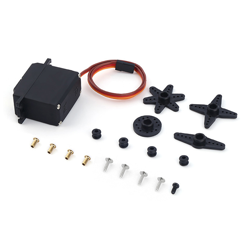
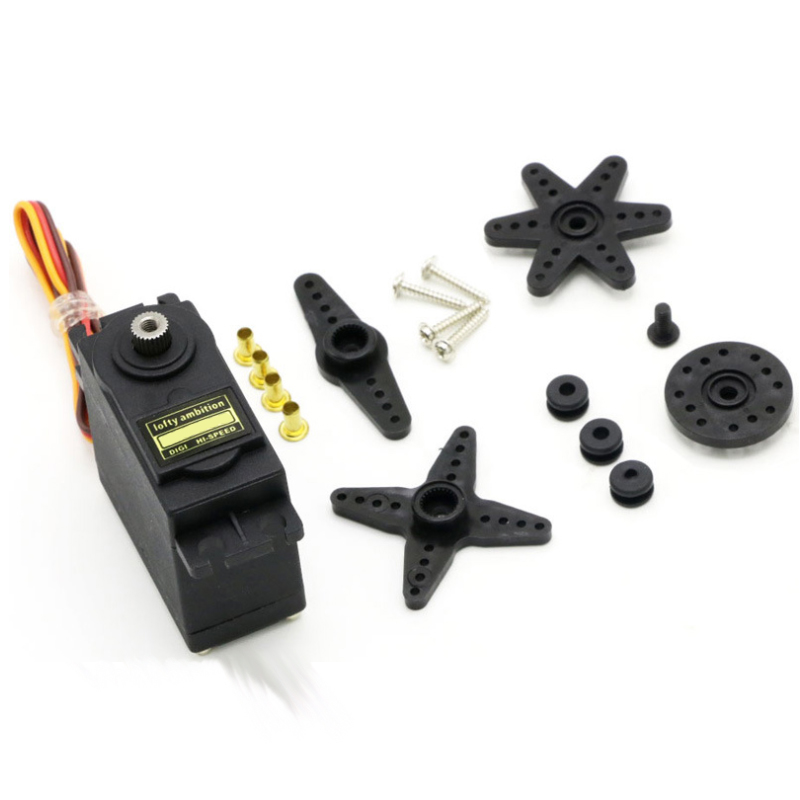
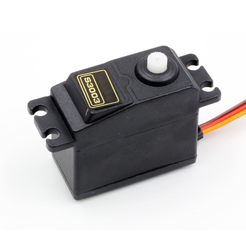
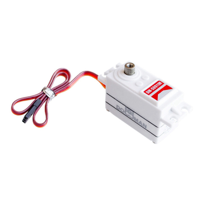
servo motor for the steering is actually a position servo driver, which is mainly composed of shell, circuit board, coreless motor, gear and position detector.
Working principle
There is a reference circuit inside the steering gear, which generates a reference signal with a period of 20ms and a width of 1.5ms. The obtained DC bias voltage is compared with the voltage of the potentiometer to obtain the voltage difference output. After judging the IC direction of the circuit board, drive the coreless motor to start rotating, transmit the power to the swing arm through the reduction gear, and send back the signal by the position detector to judge whether it is in place.
Servo Steering Robot Car
The steering gear rotation angle is realized by adjusting the duty cycle of PWM "pulse width modulation" signal. The period of the standard PWM signal is fixed at 20ms. Theoretically, the pulse width distribution should be between 1ms and 2ms, in fact, it can be between 0.5ms and 2.5ms. The pulse width corresponds to the rotation angle of 0 ° - 180 °. Different manufacturers and different models of steering gear will also be different.
PWM control of steering motor
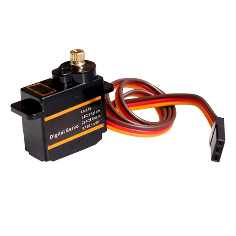
External wiring
Generally, the steering gear is externally connected with three wires, which are distinguished by three colors: Brown, red and orange. Due to different brands, the colors will also vary. Brown is the grounding wire, red is the positive wire of the power supply, and orange is the signal wire.
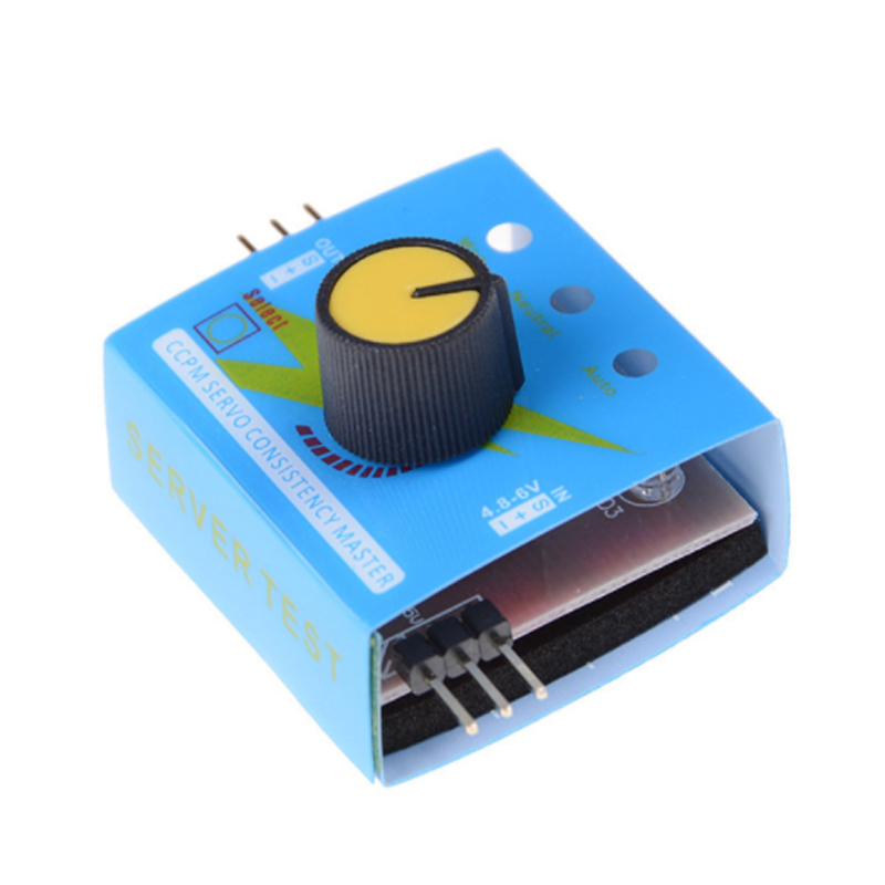
Due to the limited driving capacity of Arduino, when multiple steering gears need to be controlled, external power supply and special steering gear control board are required.


